primary clarifier design example
The entrance of the clarifier where water comes from the flocculator is the source of the flow. 952000 21623 PM Document presentation format.
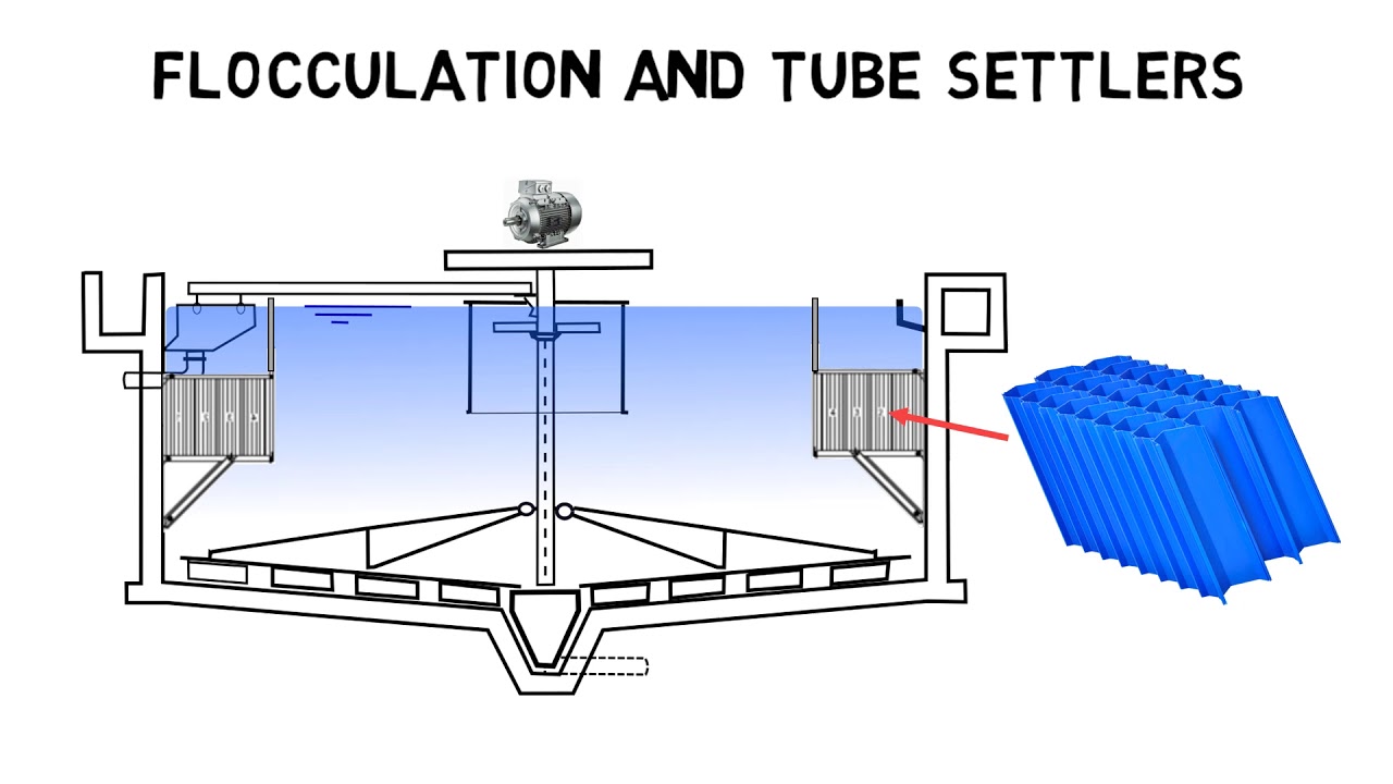
2 Cross Section Through A Typical Radial Flow Final Clarifier Adapted Download Scientific Diagram
Lessen organic loading on following biological process.
. In our clarifier as a circuit concept we will draw parallels between how electrons flow through a circuit to how water flows through the clarifier. Typical design parameters for primary clarifiers in municipal treatment Conditions Affecting Settling Factors. Overall the adoption of primary clarification units represents fewer problems on the downstream biological process operation.
For example there will be a lower quantity of oil and grease and biomass accumulation in the biological reactor minimizing possible settlements in the tank and reducing the tendency to non filamentous. Enter the email address you signed up with and well email you a reset link. FEDWA flocculating energy dissipating feedwell LA - EDI Impinging outlets Lower feed elevation.
This tool is useful in determining the dimensions of a rectangular clarifier. Remove solids that pass through headworks and grit equipment. This tool is useful in determining the dimensions of a rectangular clarifier.
Design of primary clarifiers has historically been done more empirically than rationally. Peak Design Flow 2000-3000 gpdsq. Remember me on this computer.
Process changes can also result in changes to the physicalchemical makeup of the wastewater being treated by a clarifier. This Excel spreadsheet can handle primary and secondary clarifier surface area calculations and determine diameter for circular clarifiers or length and width for rectangular clarifiers and is available in either US. Tubes made of PVC plastic are a minor cost in clarifier design improvements and may lead to an increase of operating rate of 2 to 4 times.
It will have mostly organic substances and also inorganic substances. This primary wastewater treatment sedimentation tank will produce a homogeneous liquid capable of being treated biologically and a sludge that can be separately treated or. Hydraulic Loading Rate Surface Overflow Rate Average Design Flow 800-1200 gpdsq.
Example 7-7 Design a clarifier -thickener for the pulp and paper wastewater using the testing data described in Figures 7-84 through 7-95 to accommodate an influent design flow of 10 million. Fongers Dave DEQ Created Date. Units at a very low cost only 1195 in our spreadsheet store.
The reduction in solids present in the outflow allows a reduction in the clarifier footprint when designing. Monroe Environmentals Primary Circular Clarifiers are designed to receive raw wastewater after it has been pre-screened to remove large objects and grit. For example it is not uncommon to see in many wastewater treatment plant master or facilities plans a statement such as The primary clarifiers are designed to.
9 Primary and secondary clarifiers essentially share the same primary function. Close Log In. PRIMARY CLARIFIER DESIGN CONCEPTS AND CONSIDERATIONS Because the process objective is more appropriately focused on the clarified liquid rather than the thickened underflow the unit operation discussed herein is referred to as primary clarification and the units themselves as primary clarifiers.
66 Changes in Suspended Solids Concentration. Log in with Facebook Log in with Google. This design can be utilized in primary secondary and industrial wastewater applications.
These spreadsheets also make weir overflow calculations to aid in effluent weir design. 11 However based on the design parameters listed above we can examine some fundamental 12 differences between primary and secondary clarifiers. The average surface overflow rate for a.
They also have similar configurations and designs. This is called primary sludge PS. Primary clarifiers reduce the content of suspended solids and pollutants embedded in those.
The expected range for percent removal in a primary clarifier is 90-95 settle able solids 40-60. The AguaClara treatment train is designed so that flow is driven by potential energy. The main reason for this is a lack of understanding of what pollutants primary clarifiers are capable of removing.
Clarifiers for Package Plants With Brush Rotor Aerators Peripheral Influent Central Influent PRIMARY CLARIFIERS TYPE I II SEDIMENTATION PRIMARY PURPOSE. Other EDI examples NEWEA Optimizing Clarifier Performance Are We Designing the Clarifiers Right. These are drawn out from the conical floor of the clarifier.
To remove 10 solids from water using sedimentation. The following criteria are recommended for design. In order to maintain and.
Clarifier Calculations Last modified by. 521 Primary Clarifiers Primary clarifier designs are primarily based upon surface overflow rate. Primary Clarifier Design Calculation The clarifiers are used in water and wastewater treatment process to remove suspended solids from water under the sole influence of gravity.
Concentration of Solids- The larger and heavier the suspended solids the faster they will settle. Feed discharge vertically without restriction. The Primary Clarifier will be designed for the following process design parameters.
Floatable material scum are removed from the surface by skimmers and settle able solids sludge are collected on the bottom by a rakes. Primary Clarifier Primary clarification is the physical treatment process of removing solids before biological treatment. January 27 2016 11 From WEF 2005 Clarifier Design Manual of Practice No.
If WAS is returned to the primary then. The more particles there are within design the better the settling. Water then moves through the clarifier and exits to the.
For example a clarifier designed to receive the wastewater discharge from a small heavy metal precipitation system will not be able to properly treat larger wastewater volumes for removing chrome from a tannery effluent. Primary sludge When raw sewage is settled in a primary clarifier the suspended solids settle down by gravity.